Retaining Wall Design
Overview
The RetwallDesign module provides a comprehensive solution for the design and analysis of retaining structures and abutment walls. Built on widely practiced earth pressure analysis concepts, this module delivers a unique and efficient workflow for analyzing long retaining walls with varying section geometries.
The module verifies structural safety against multiple failure modes including overturning, sliding, and excessive heel/toe pressure beyond allowable bearing capacity. While it does not perform detailed structural analysis of individual components, it excels at segment-based analysis, allowing each section of a long retaining wall to be designed with specific height and bottom width parameters tailored to local conditions.
Design Conventions
Understanding the following conventions is essential for effective use of the Retaining Wall Design module:
- Measurement Reference: All water table elevations and fill heights are measured from the base of the wall.
- View Orientation: Section views (unless in Flip Mode) are presented from left to right, facing the beginning of the alignment route.
The following sections present a systematic workflow for retaining wall design, with each step building upon the previous to guide you from initial object preparation through final documentation and presentation.
Preparing Prerequisite Objects
Before initiating a design session, you must prepare the necessary AutoCAD objects. The Module Browser dialog will outline these prerequisites during session definition.
Creating the Layout Object
Draw the layout object following the footprint of the wall toe (front face edge) in plan view within AutoCAD. Once drawn, create profile data for the alignment object, ensuring:
- Adequate offset locations in the transverse direction are included for comprehensive cross-sectional representation
- Fine resolution is maintained, typically with 2 to 5 meter incremental intervals, to allow proper segmentation and analysis
Note: Avoid using curves in alignment objects for retaining walls, as they produce inaccurate results in plan views and bill of quantities. If curves exist in your design, represent them using sufficient vertices for adequate linear approximation.
Preparing Wall Profile Objects
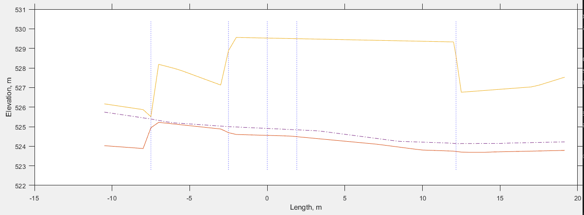
Create wall top and bottom profile objects to define the varying elevation along the wall length. This is most efficiently accomplished by overlaying the profile plot generated from the layout object.
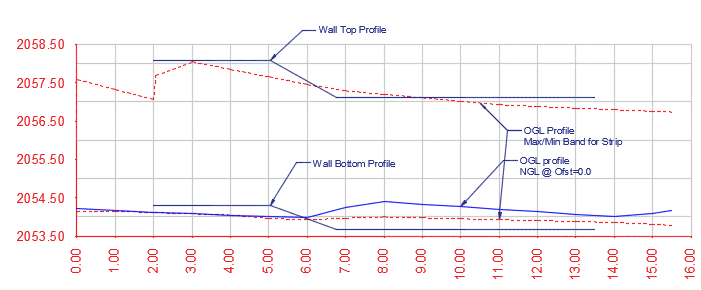
Profile overlay showing wall top and bottom definition.
These profile objects are essential for retaining walls with varying heights along their length, such as abutment walls for diversion weir structures. For walls with uniform height, simple polylines can represent the top and bottom profiles.
Important Considerations:
- Ensure sufficient length of uniform wall height at each segment. Insufficient uniform sections may cause processing failures in subsequent steps.
- Begin the wall with uniform height for a minimum distance of five times the incremental distance used in profile generation.
Defining and Starting a Design Session
With prerequisite objects prepared, you can now establish your design session.
Clear the iCAD workspace using Workspace > Clear Workspace or press CTRL+0. Then launch the Module Browser from Workspace > Create and Run Session or use the toolbar icon.
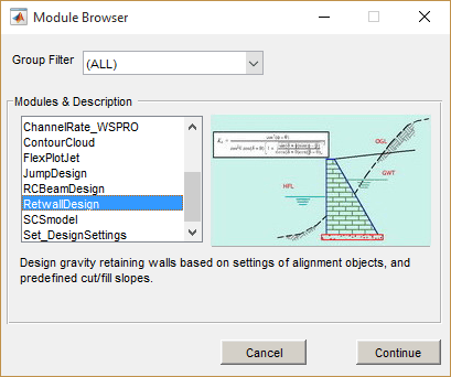
Module Browser showing RetwallDesign module selection.
Select the RetwallDesign module from the Module Browser dialog. In the New Session dialog that appears, click on the Wall Alignment Object entry in the left panel. AutoCAD will enter selection mode—pick the wall layout object you prepared earlier.
Once the selection is accepted, the session is fully defined. Click the Run Session button to launch the elevation view in the main iCAD interface.
Working with Simple Walls
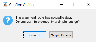
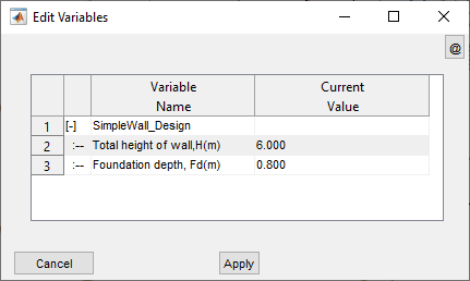
If your wall alignment object lacks profile data, you can proceed with a simplified design approach. When prompted, select Simple Design and provide basic wall height and foundation depth values.
Simple wall design parameter input dialog.
Enter the required dimensions to generate the elevation view.
Elevation view generated for simple wall design.
Simple Wall Limitations:
- Bill of quantities includes only the wall structure; earthwork volumes are not calculated.
- Plan view generation is not available for simple wall designs.
Working with Complete Profile Data
When profile data is available, the interface displays comprehensive information including centerline profile data, maximum and minimum transverse elevations, and wall face-break points.
Plan view of retaining wall alignment for a diversion weir structure.
Initial elevation view showing complete profile data and wall face-break lines.
Note: Vertices placed in the alignment drawing within AutoCAD define face-break locations along the longitudinal dimension of the wall, establishing natural segment boundaries for the design process.
Identifying Design Segments
For simple wall designs, the wall face is automatically displayed and you may proceed to the next step. For complex walls with complete profile data, you must define wall levels before segment identification.
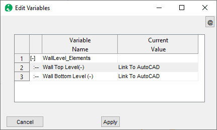
Defining Wall Levels
Navigate to Workflow > Pick Wall Levels. Click on the Wall Top variable value, switch to AutoCAD, and select the object representing the wall top level. Repeat this process for the Wall Bottom Level variable, selecting the appropriate wall bottom object.
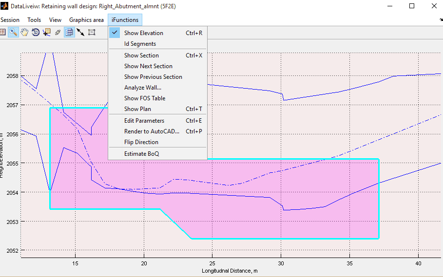
Refresh the view using Workflow > Refresh View or press CTRL+R. The wall face should now appear shaded in the profile view.
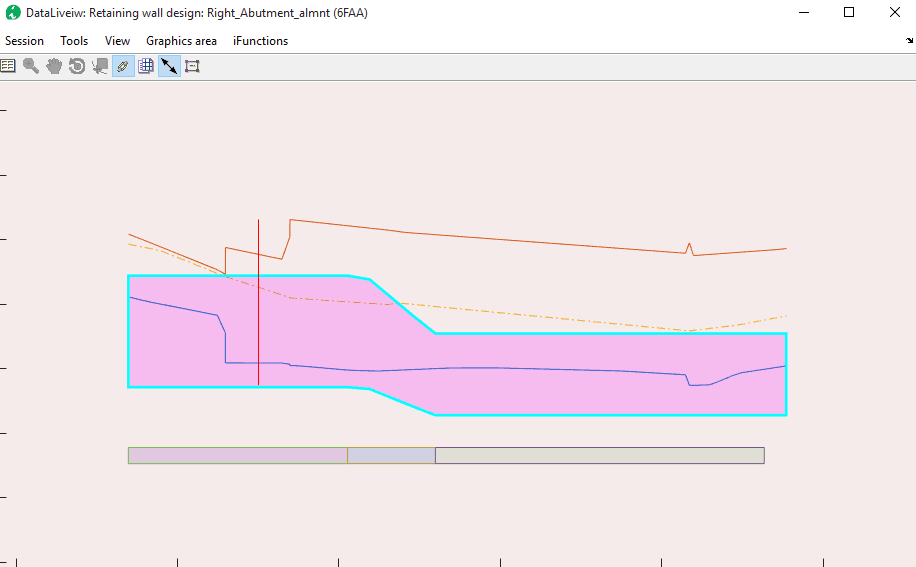
Profile view showing the defined wall face after level specification.
Automatic Segment Identification
Execute Workflow > Id Segments to automatically identify design segments based on wall height variations. The module analyzes wall height at incremental stations and groups locations with similar heights into distinct segments. Upon successful identification, segments are displayed schematically at the wall base, each distinguished by a unique color.
Wall elevation showing identified segments with color coding.
Segment Identification Requirements: Each segment must contain at least three incremental stations. If this requirement is not met, the system will flag an error as shown below. In such cases, exit the design process and re-extract profile data with finer incremental intervals.
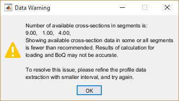
Error notification for insufficient segment resolution.
Configuring Design Parameters
The module requires comprehensive parameter configuration across multiple categories to ensure accurate analysis and design. Access the variable editor from Workflow > View Variable Editor to configure all necessary inputs.
Load Elements Configuration
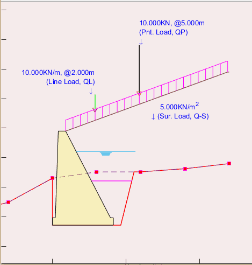
Variable editor showing load element configuration options.
Define the environmental and loading conditions that will influence wall behavior using the parameters outlined in the table below.
| Variable Name | Description |
|---|---|
| Ground Water Height (m) | Height of water table in the backfill material behind the wall |
| Intermediate Backfill Height (m) | Height of intermediate backfill material |
| Passive Backfill Height (m) | Height of fill material in front of the wall toe |
| Drain Water Height (m) | Height of water level in front of the wall toe |
| Surcharge Load (KN/m²) | Uniformly distributed load magnitude |
| Line Load (KN/m) | Line load applied along the length of the wall |
| Point Load (KN) | Point load applied on top of fill material |
Important Notes:
- All load element heights are measured from the base of the wall
- External loads are applied on top of the backfill material
Wall Geometry and Orientation
Configure the physical characteristics of the retaining wall structure using the parameters detailed below.
| Variable Name | Variable Description | Remarks |
|---|---|---|
| Top width of wall, Tw (m) | The top width of the abutment wall | |
| T-Shape Dims (m) | [Toe, Stem width, flare, Heel] Wall dimensions specifying the shape and geometry of the wall body including the footing. | Use [0, 0] for simple gravity wall. See notes below this table on how to define different shapes. |
| Footing Thickness (m) | Thickness of footing block | |
| Wall friction angle (Deg) | Wall friction angle denoting the backfill vs back of wall interaction | |
| Default B/H ratio (-) | Default ratio to determine the bottom width of the retaining wall as a function of the wall height. | This value is used to schematically draw the wall before actual designed width is assigned. Once a design value is assigned, this ratio is not used. |
| Side Cut slopes, (-) | [Bcut, mut, hcut] values to specify earth cut slope See illustration below. Bcut or Bfil: Flat space from cut edge Mcut or mfil: cut slope after flat space Hcut or Hfil: Height of cut | |
| Backfill Slopes, (-) | [Bfil, mfil, Hfil] values to specify earth fill slope | |
| Wall face direction, (-) | Wall face direction 1: Orient wall to the left -1: Orient wall to the right | Direction set with reference to face looking at end of alignment route. See notes on presentation and documentation section, and the plan view details to learn about the difference. |
The illustration below provides a schematic representation of all retaining wall variables described above.
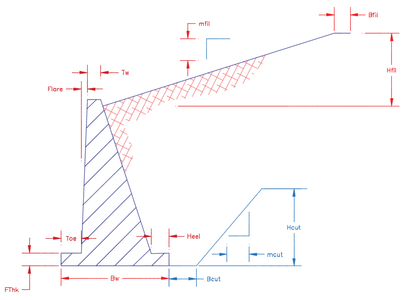
Schematic showing all retaining wall geometric parameters and their relationships.
The following examples demonstrate various wall configurations achievable through parameter adjustment (shown with Tw = 0.5m):
Example of a gravity wall configuration.
Example of a T-shaped cantilever wall configuration.
Example of a semi-gravity wall configuration.
Material Properties
Define material characteristics that govern load magnitudes acting on the wall structure. The module includes a built-in library of common materials with reference values to guide your selections.
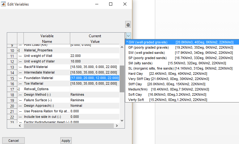
Material specification interface with built-in reference parameters for common soil types.
Configure material properties for all components affecting wall behavior:
| Variable Name | Variable Description |
|---|---|
| Unit weight of Wall | Unit weights of the retaining wall material |
| Unit weight of Water | Unit weight of water |
| Backfill, Intermediate, Foundation and Toe Material | [γ, ϕ, c, γ_sat] values for earth materials, where: γ is bulk unit weight [KN/m³] ϕ is angle of friction [deg] c is cohesion [KN/m²] γ_sat is saturated unit weight See note below. |
Analysis and Design Options
Configure the analytical approach and computational assumptions for the wall design:
| Variable Name | Variable Description | Remarks |
|---|---|---|
| Design Method (-) | Design method to be used in analysis: Rankine's Coulombs | Apply either Rankine's or Coulombs methods to determine the active and passive earth pressure on the wall |
| Failure Surface (-) | Assumed failure surface for analysis, defining the application point of earth pressures | Rankine's method assumes forces are applied on the vertical plane passing through the heel of the wall Coulombs method assumes earth pressures are applied on the back of the wall. |
| Design Approach (-) | One of available design options: Nominal DA-1 (Euro Code) DA-2 (Euro Code) | These approaches establish the load and moment factors to be applied from known practices to determine safety against failure. See technical notes further below for details. |
| Use Poisons Ratio for Kp at Rest (v) | Poisons ratio value to determine passive pressure at rest condition | See technical notes below for the relationship used. |
| Include toe side in cut (-) | Include or exclude cut volumes in bill of quantity estimates | |
| Factor Hydrodynamic Head (-) | Consider or ignore hydrodynamic head in pressure analysis | If ignored, hydrostatic pressures is considered factoring the depth of water at the heel and toe of the retaining wall. |
| Bottom Width Limits (bwLims) | Whether to limit bottom width dimension input for valid geometry in plan view | If set to None, no limits apply. It can also be set to Alignment Vertices to Automatically set valid limits. |
| Segment Id Source (-) | Determines how wall segments are identified. It can be set to either of Alignment Vertices or WTBL Vertices. | If available, using the WTL and WBL objects from AutoCAD is strongly recommended. |
| BoQ Listing (-) | Dictates how BoQ is generated. It can be set to Detailed or Summary | Detailed BoQ lists all items of work for each segment. While Summary option rolls up all quantities of each segment into individual items of work. |
The module provides built-in parameter lists derived from referenced literature to streamline data input. An example of foundation material selection with preset values is shown below:
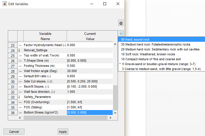
Built-in shear stress definition settings for common foundation materials.
Safety Parameters
Establish acceptance criteria for structural stability evaluation:
| Variable Name | Variable Description |
|---|---|
| FOS (Overturning) | Desired range of values for factor of safety against overturning. [1.5, Inf] input evaluates safety against minimum of 1.5. |
| FOS (Sliding) | Same but against sliding |
| Bottom Stress (kg/cm²) | Allowable bearing capacity of the foundation material [kg/cm²] |
Note on Safety Evaluation:
- Safety parameters define the acceptable minimum and maximum values. Analysis results within these ranges receive a PASS flag, while results outside these ranges receive a FAIL flag in the analysis report.
- Preset materials are available to assist in selecting appropriate values, or you may specify custom values as needed.
Designing Wall Sections
Section design workflow interface.
With parameters configured and segments identified, you can now design the wall sections to achieve structural stability.
Accessing Cross-Section View
From the elevation view, navigate to Workflow > Cross Section view or press CTRL+X. The interface enters interactive mode, allowing you to select a location for cross-section analysis. Click on any region with uniform wall height.
Note: The selected location is automatically rounded to the nearest incremental station recorded during profile extraction, and the corresponding cross-section is generated.
Determining Design Width
Select Workflow > Design Wall… to access the design solution guide, which displays bottom width values that satisfy the required safety parameters.

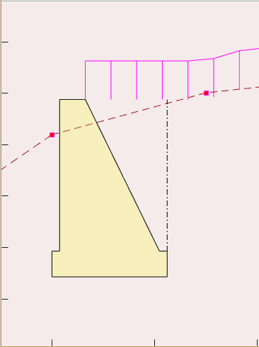
Design solution guide showing safety parameter satisfaction across different bottom widths. In this example, overturning and sliding factors of safety are met below 1.5m width, but eccentricity requirements are only satisfied beyond 2.0m.
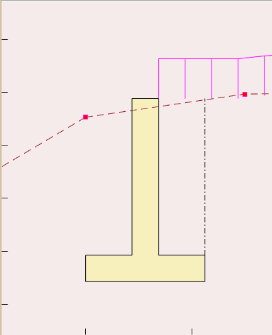
Use the Pick A Scene Solution toolbar to select a desired width. The cross-section view updates automatically to reflect your selection.
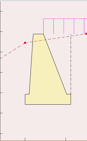
Cross-section view showing selected wall geometry.
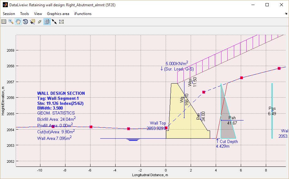
Design parameters and dimensions displayed in cross-section view.
Analyzing Wall Performance
Select Workflow > Analyze Wall… to perform detailed analysis of the cross-section using current settings. This generates comprehensive loading diagrams and a summary of safety evaluations.
Navigation Tip: Move between incremental stations using
Shift+.(forward) orShift+,(backward).
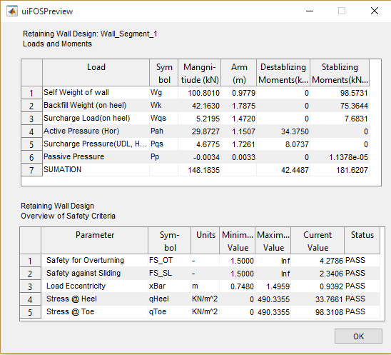
Verify that all design parameters achieve satisfactory performance, indicated by PASS flags in the lower summary table.
Analysis results showing loading diagrams and safety evaluation summary.
Adjusting Design Parameters
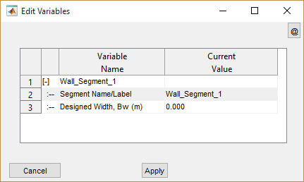
If safety requirements are not met, adjust the bottom width using the variable editor. Access it from Workflow > View variable Editor or press CTRL+E. The compact editor window allows you to modify design segment information directly.
Segments without assigned bottom widths display 0.000. Once you assign a design value, the module retains this value for subsequent operations. Enter your desired bottom width and/or segment label, then click the Apply button.
Transition Walls: Walls with variable height (transition walls) cannot be directly analyzed. However, you can assign bottom widths based on design results from adjacent uniform-height sections. Specify transition wall widths in pairs, for example [2.5, 3.0], indicating a uniformly varying bottom width from 2.5m at the start to 3.0m at the end.
Repeat the analysis and adjustment process iteratively until all segments achieve satisfactory performance against the established safety parameters.
Saving Your Work
Preserve your design progress by saving the session using Session > Save from the menu.
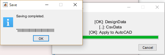
Session save interface.
Presentation and Documentation
Upon completing the design for all identified segments—including transition walls—you can leverage comprehensive presentation and documentation tools to communicate design details effectively.
Available Output Options:
- Standard report and bill of quantities (BoQ) generation functions
- AutoCAD drawings including elevation, cross-sectional, and plan layout views
Standard Output Functions
The module fully integrates with iCAD's standard finishing and presentation workflow, providing:
Design and Analysis Reports: Generate comprehensive documentation from Sessions > Build Report, capturing all design decisions, analysis results, and safety verifications.
Bill of Quantities (BoQ): Create detailed quantity estimates from Workflow > Generate BoQ.
Complete BoQ Generation: To ensure comprehensive quantity listing, verify that all segments have satisfactory bottom width assignments, navigate through all cross-sections from beginning to end, and generate the plan view before creating the BoQ.
Generating AutoCAD Drawings
The module supports AutoCAD output for transverse and longitudinal cross-section views. Refer to the finishing solutions section of the user manual for detailed instructions on generating these drawings.
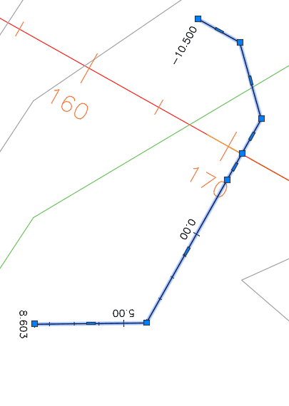
Generating Plan Views
Plan views represent a critical output from this module, essential for creating layout information overlaid on topographic maps and providing positioning details for construction drawing albums.
Ensure all segments have appropriate bottom width assignments before proceeding. Navigate to Workflow > Show Plan or press Ctrl+T to generate the plan view. The system maintains the orientation established by the layout object.
Use the Generating Additional Plots to AutoCAD option to export the plan view to AutoCAD for further processing and inclusion in drawing sets.
Plan view showing complete wall layout with surrounding terrain.
Detailed plan view with dimensional annotations.
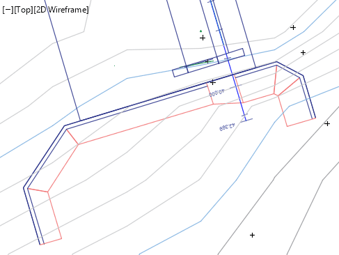
Plan view integrated with topographic information.
Wall Face Direction: The plan view orientation can be reversed by setting the Wall Face Direction variable under Retwall Settings group to -1 (Right). Select the orientation that best suits your project context.
Best Practices for Plan View Generation
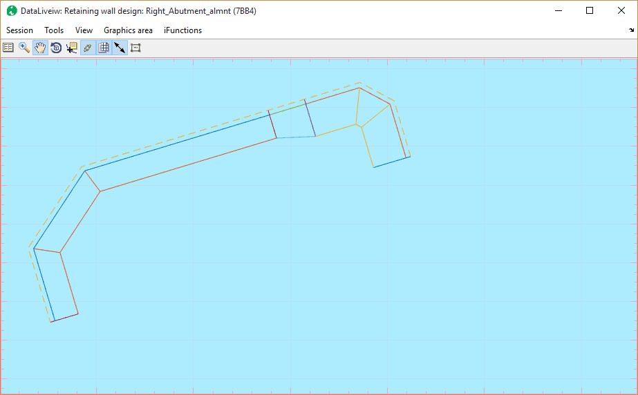
Plan view generation requires proper alignment between vertices in the layout object and those in the wall top/bottom profiles. Misalignment can result in unrepresentative geometry as shown below:
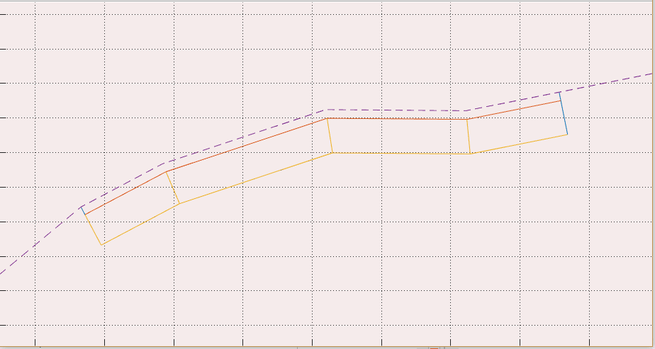
Example of distorted plan view geometry due to vertex misalignment.
This issue commonly occurs when wall top/bottom profile objects are created after the alignment route and profile extraction are completed.
Note: Alignment routes generated using the JumpDesign module during weir design are automatically configured to avoid such issues.
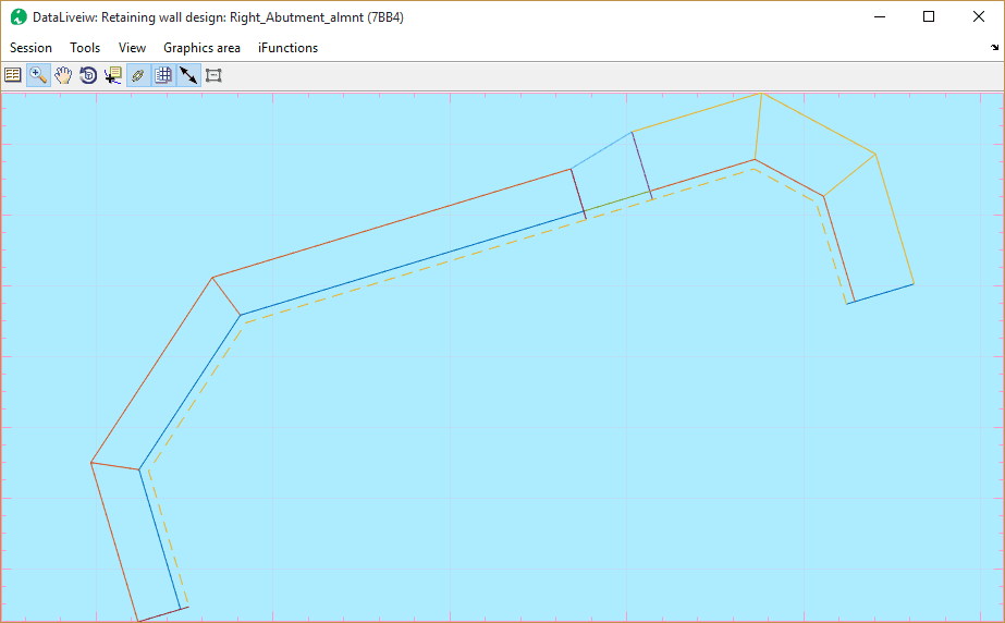
When vertices are properly aligned, the plan view renders correctly:
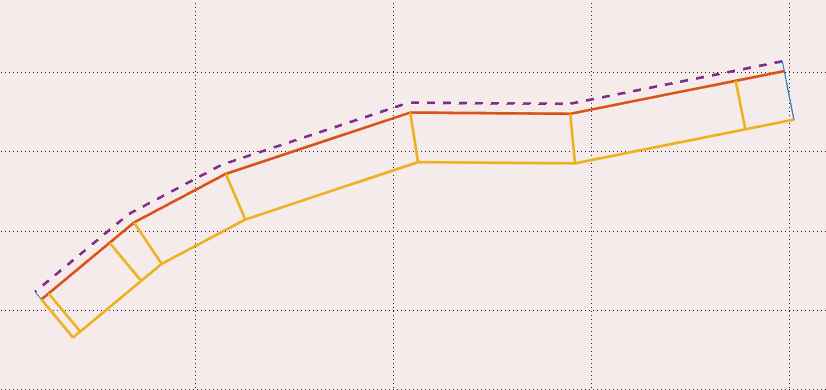
Properly rendered plan view with correctly aligned vertices.
Recommended Workflow for Object Preparation:
Draw the layout object overlaying your base map. Mark station locations at appropriate intervals (e.g., 0.25m, 0.5m, 1.0m). Identify the beginning, end, and interim points for the retaining wall, ensuring vertices are placed at these exact locations.
Extract the profile with your desired offset settings and save the profile data. Before closing the profile view, copy the graphics for AutoCAD plotting using Tools > Copy Graphics, then plot to AutoCAD via Tools > Plot to AutoCAD (or CTRL+P) at a scale of 1.0.
Draw the wall top and bottom level geometries using the vertex locations established in the previous steps. Design sessions defined using layout objects and profiles prepared in this coordinated manner will produce accurate geometries.
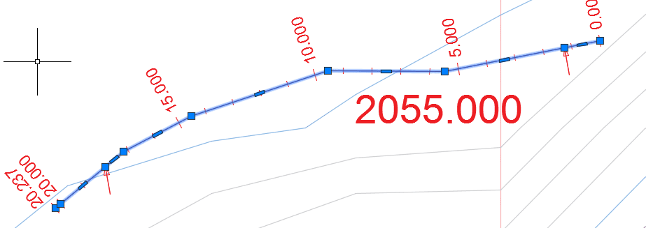
Proper vertex alignment at stations 1.25m and 18m, matching wall top and bottom profile endpoints.
Important Notes:
- Wall top and bottom profiles must have the same number of vertices.
- Profile segments extending beyond the profile data range are automatically trimmed.
- Walls may render incompletely if WallTop and WallBottom coordinates do not begin and end at profile data boundaries.
Pro Tip: Ensure vertex synchronization by aligning wall top/bottom profile vertices to stations that are easily identifiable on the layout object. Subsequently, edit the layout object to add vertices at these locations and re-extract the profile.
Technical Notes
The module employs a segment-based analysis approach, identifying design zones along the wall alignment based on height variations. Each segment is analyzed independently to determine the optimal bottom width required for structural stability.
Earth Pressure Calculation
Earth pressure on the wall is computed using the fundamental relationship:

Basic earth pressure calculation formula.
Where γ represents the unit weight of backfill material, H is the backfill height, and Ka and Kp denote active and passive pressure coefficients respectively, determined by the selected analysis method.
Rankine's Method
The active pressure coefficient under Rankine's concept is determined from established relationships (Hunt 1986, Arora 2004, Geo5 2005-2017):
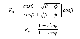
Rankine's active earth pressure coefficient formula.
Coulomb's Method
Active pressure under Coulomb's concept follows an alternative formulation:
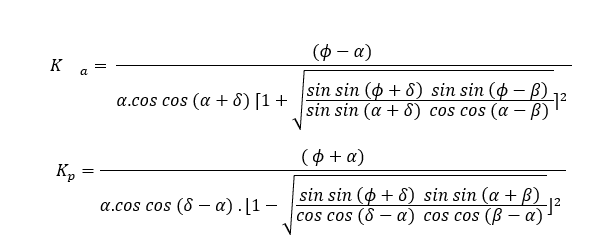
Coulomb's active earth pressure coefficient formula.
In these equations, φ represents the angle of internal friction, α is the back face inclination of the structure, δ is the soil-structure friction angle, and β is the backfill inclination relative to horizontal.
Calculation Assumptions:
- Pressure coefficients are computed for cohesionless soil conditions
- For passive pressure conditions, δ = β = 0 is assumed
Failure Surface Assumptions
Rankine's method assumes a virtual vertical plane at the wall heel where earth pressure acts at an inclination equal to the backfill slope angle. Conversely, Coulomb's method typically assumes forces act directly on the wall back at an angle incorporating the soil-structure friction coefficient.
The module provides flexibility in specifying failure surfaces independent of the pressure coefficient calculation method, allowing you to tailor assumptions to your specific design requirements.
Pressure Coefficients for Cohesive Soils
Coulomb's theory extends to cohesive soils, providing modified coefficients for active earth pressure:

Active earth pressure coefficient for cohesive soils.
The corresponding tension crack depth is determined from:

Formula for computing tension crack location in cohesive soils.
In these relationships, γt represents the unit weight of backfill material, ceff is the effective cohesion, Kac is the pressure coefficient attributed to cohesion, and Ka is the active earth pressure coefficient. The computed crack depth ho is constrained to not exceed either the topmost layer thickness or the depth to the water table, whichever is smaller.
Hydrostatic and Hydrodynamic Pressure
Hydrostatic pressure resulting from groundwater is calculated using the standard relationship:

Hydrostatic pressure calculation formula.
When a hydraulic gradient exists across the wall, hydrodynamic pressure is computed from the gradient-based relationship:

Hydrodynamic pressure calculation incorporating hydraulic gradient.
In this formulation, hw represents the difference in water surface elevation, while dd and du denote the water table depth at the heel and toe sides respectively.

Pressure calculation accounting for saturated soil conditions.
Where γsat represents the saturated unit weight of the soil mass.
Pressure from External Loads
External loads applied on the backfill surface induce additional pressure on the retaining wall. The module computes pressure distributions for three load types:
Uniformly Distributed Loads
Surcharge loads uniformly distributed across the backfill surface generate lateral pressure computed as:

Lateral pressure from uniformly distributed surcharge loads.
Where qs is the applied surcharge load [KN·m-2] and K0 is the at-rest earth pressure coefficient.
Line Loads
Line loads parallel to the wall generate pressure distributions according to:
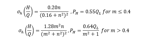
Lateral pressure distribution from line loads, where n and m are geometric distance factors.
Point Loads
Concentrated loads on the backfill surface produce pressure distributions computed from:
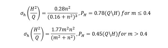
Lateral pressure distribution from point loads.
Eurocode Partial Factors
When applying European code provisions, load factors are applied according to the selected design approach. The table below summarizes applicable partial factors:
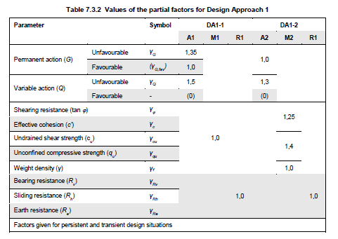
Values of partial factors in Design Approach 1 (DA1-1, DA1-2) per Eurocode (Andrew J. Bond, 2013).
These factors are applied to compute the vertical and horizontal components of active pressure acting on the wall structure.
Stability Analysis
Wall stability is verified through a comprehensive five-parameter assessment examining resistance to overturning, sliding, eccentric loading, and bearing capacity exceedance. The governing relationships are:
Factor of safety calculations for overturning and sliding.
Load eccentricity calculation determining resultant force location.
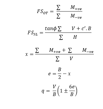
Bearing pressure calculations at wall toe and heel.
In these equations:
- ΣM~-ve~ = summation of destabilizing (overturning) moments
- ΣM~+ve~ = summation of stabilizing (resisting) moments
- ΣV = summation of vertical forces
- B = bottom width of the wall
- e = load eccentricity
- c' = cohesion of foundation soil
- q = bearing stress at the wall base (toe and heel)
Geometric Limitations
The RetwallDesign module accommodates a wide range of wall configurations including T-shaped cantilever walls, semi-gravity walls, and gravity walls, subject to the following constraints:
-
Foundation Geometry: The module analyzes walls with horizontal base configurations only.
-
Wall Height Limitations: For walls exceeding 7 meters in height, professional technical guidance is strongly recommended to ensure appropriate application of design principles.
-
Computational Boundaries: The analysis may terminate with errors if calculated cut profiles do not intersect the natural ground level. This typically occurs when bottom width dimensions become excessively large relative to the wall geometry and site conditions.